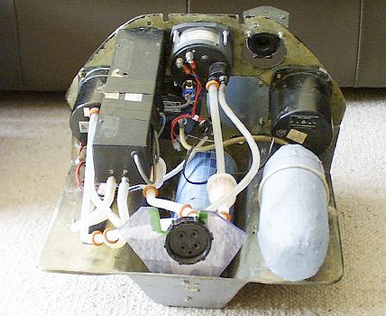
The rear of the panel as it was when I bought the glider.
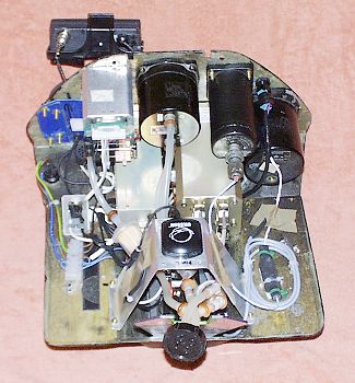
The rebuilt panel.
|
|
|
The rear of the panel as it was when I bought the glider. |
The rebuilt panel. |
The GPS uses an active antenna, which is mounted on top of the sheet alloy cross piece to give it an unobstructed view of the sky through the glass fibre nose. The data interconnection box is in the well below the antenna with the C4's audio output mounted in the well beyond the interconnect box. If an iPAQ is substituted for the GPS II+, a blind GPS would replace the active antenna. The connector on the left of the panel receives power from the batteries. The connector for the radio microphone and speaker, mounted on a support made from 1.5mm fibreglass sheet, is just inboard of the power connector. The transmit switch is mounted on the stick. It plugs into a connector on the bottom of the panel between the internconnection box and the C4 speaker. The R.C. Allen T&S is a 28v unit. It is driven via a solid state 12v to 28v converter which is mounted to the right of the antenna support and surrounded by the cable leading to the C4's temperature sensor.
 |
|
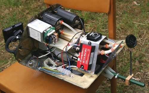
The rebuilt panel with FLARM installed. |
As the Binatone B.350 PNA has its own internal antenna, I simply reused the original sheet alloy cross piece and the Gilsson active GPS antenna I'd used with the Garmin GPS II+ and bolted the Red Box FLARM electronics to one leg of the cross piece. Since the active antenna's cable no longer needed to reach a GPS receiver on a flexi-mount in front of the panel, I was able to shorten it considerly and hence tidy up some of the the wiring. The Red Box's transceiver dipole is mounted on an outrigger attached to the Libelle instrument tray. This allows it to be positioned midway between the instrument tray and the rudder pedals and hence to get a relatively unobstructed view back past the instruments.
 |
|
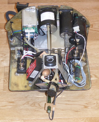
Panel with new PNA and 8.33kHz radio. |
I'd found that the XLR plug that powers the panel could cause instrument resets if it was knocked or kicked, so I fitted a 2000 uF capacitor in seres with a 2 ohm, 10w wirewound resistor across each of the two 12v positive lines (one for each battery) and the common ground line. This has eliminated the problem. The antiglitch filters are out of sight under the Dittel KRT2 radio to the right of the XLR power inlet socket, which is on the left just in front of the panel's rear face, with blue, green and yellow cables attached to it. From the antiglitch filters the positive lines go through their respective fuses and thence to the black plastic power distribution boxes visible on each side of the instrument tray.
The four wire connector on the same side as the power input socket and mounted on a white epoxyboard support, connects the speaker and microphone, which are mounted on the starboard cockpit wall alongside the seat, to the radio.
The distribution box in front of the speaker/microphone connector powers the Borgelt B.40 backup vario, Red Box FLARM and its GPS antenna. It also supplies power to a metal data distribution box, which is invisible beneath the alloy bridge that supports the RedBox FLARM and antenna.
The distribution box on the right powers the Dittel KRT2 radio and the T&B blind flying instrument. The coiled grey cable in front of it connects the black temperature sensor, above the cable at the front, to the SDI C4.
The metal box, invisible under the GPS antenna support structure, contains a 3 Amp 12v to 5V DC converter that powers a Medion S.3747 PNA, running the LK8000 navigation system. It also provides 12v power to the SDI C4. The box still contains data lines that formerly connected a Garmin GPS II+ to a logger and the C4. The logger is now self-contained and mounted behind the cockpit on the battery box lid.
The C4 looses quite a lot of functionality without a GPS data feed because there is no longer anything in the panel that can provide both GPS position data and the NMEA sentences used to pass the task description to it. Fortunately, LK8000 provides all these missing information.
The support for the FLARM transceiver antenna now has a 1.6mm square spruce strip expoxied to its top surface. This ensures that the wooden block always keeps its dipole upright.