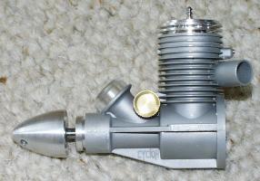
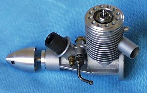
The Cyclon-06 TOP-2.
This example has the standard dome headed hex prop nut
replaced by a solid spinner.
This makes using a starter easier.
| |
|
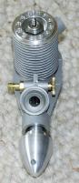
The Cyclon-06 TOP-2.
|
 |
|
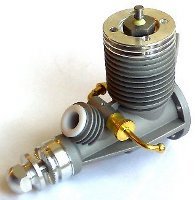
Cyclon-06 TOP-4, 2010 model |
Cyclons are produced by Alexander Kalmykov in Novosibirsk, Russia. They typically turn an APC 6 x 2 at 30000 rpm. It is a very well made engine using AAC technology and Nelson plugs. It is designed for radial mounting and weighs 71g in standard form. There is a choice of left, rear or right exhaust stack (TOP-2, TOP-3, TOP-4 models).
Dave Clarkson was instrumental in getting the Cyclon-06 into production. He's known Alexander for a long time - at least since he was the speed World Champ. Alexander sent him a prototype 06 and Dave told him why it wouldn't do and described exactly what was wanted. The result was the Cyclon-06 TOP-2 engine. Initial production was a batch of 10 engines imported to the UK by Dave Clarkson.
Cyclon engines are available directly from Aleksandr Kalmykov in Novosibirsk or visit the Cyclon web site. Prices at Jan, 2002 were $179.00 one off or $964.00 for a batch of 10. The engine is also available from Doug Galbreath in the USA. Contact Doug by phone: +1 916 757 2283 or take a look at his online catalogue.
There are currently several versions of the engine. The main differences are in the crank case casting, though individual engines show detail differences. All internal parts are said to be interchangeable though they may vary from batch to batch due to Alexander Kalmykov's incremental development policy. The table shows the principal differences:
|
Version |
Recognition features |
|
Cyclon-06 TOP-2 |
Has a single round exhaust stack on the left rear of the engine. All cylinder fins are the same diameter |
|
Cyclon-06 TOP-3 |
Rear exhaust engine. The stack is initially rectangular, stepping out to circular at the rear. Early examples had large diameter fins at the top of the barrel, becoming smaller one third of the way down. Current production has the TOP-2 fin design |
|
Cyclon-06 TOP-4 |
Has a single exhaust stack the same size and shape as the exhaust port on the right rear of the engine. The stack on earlier models had a flat top and bottom with rounded vertical sides. Later models have a stack with a rectangular cross section. All cylinder fins are the same diameter. |
The head screws into the main casting. It ends with a boss that slips inside the liner. When the plug, which is tight in the threads, is screwed fully home it expands the light alloy to improve the head to liner seal. You MUST remove the plug before unscrewing the head or you can cause serious damage.
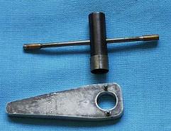
The head has a deep hole in the top, the full depth of the plug body, so that only the plug's terminal protrudes above the top of the head. Consequently you'll need a special plug wrench that can fit into this restricted space. I have a 3/8" socket (part of the 1/4" series drive series) that has been turned down to fit into the head. It was drilled transversely with a 3.5mm hole and I made a captive tommy bar that slides in the holes from a length of 3mm piano wire with a piece of brass tube sweated on each end as a keeper.
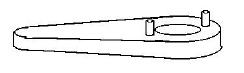
You'll need a special head wrench as well. The engine follows Russian team race practice in having a ring of holes drilled in it. The correct wrench is made from 6mm alloy scrap with two pins pressed in and spaced to fit diametrically opposite holes in the head. My wrench is drilled so the plug spanner fits through it. This way you can hold the engine with the head wrench while you change plugs without stressing the engine mounts.
Here's a sketch of the head wrench and a photo of both tools which should make this plain:
Doug Galbreath sells a head wrench and plug socket that are similar to mine. His head wrench is a steel ring with 4 pins and a threaded in handle, also made from steel. The plug wrench is a 1/4" drive 3/8" socket, turned down to fit into the head depression and through the wrench the same as mine does. If you don't want to make your own tools this set could be the way to go.
Alexander Kalmykov does sell a head wrench and plug spanner but I wouldn't recommend them because you can't use the head wrench to stop the clamp ring unscrewing while you remove the plug.
The first engines were supplied with a cute gold plated Taiwanese copy of the Nelson plug, but that supply has dried up and the most recent engines have arrived without plugs. Nelson plugs are excellent - they last well and make a good seal. If you haven't seen them, they are not interchangeable with any other plug. They cost around $2.50 each. The thread is bigger diameter and the bottom of the plug is a flat area with chamfered edges. I think the plug fits a standard 3/8" socket but do check this! The chamfers form the seal when screwed home and the flat plug surface forms the top of the bubble chamber in the head. If you have no other sources, try Henry direct:
| Address: | Henry Nelson |
| RD2 | |
| Box 233 Ramsey Road | |
| Zelienople | |
| PA 16063 | |
| U.S.A. | |
| Phone: | +1 412 538 5282 |
Historical note: George Aldrich came up with this plug design in the early 60s, though his version seated on its flat face. Henry thought up the chamfered seal, which George said was a better setup, and got the credit for the whole plug concept. George also came up with the idea of using a tight plug to improve the head seal about the same time, but doesn't know how the Russians picked it up. All I know is that many Russian motors use this system and not too many Western ones do it.
Cyclons will only run on pressure so you'll probably want to fit a flood-off inlet. Your local model shop should sell a suitable 3mm brass nipple (designed for use as a muffler pressure tap) that can be fitted by drilling and tapping a hole into the venturi housing below the plastic insert. The latter is a press fit that I haven't yet tried to remove. If you want to fit the flood-off nipple to the left side of the venturi you'll need to replace the standard needle otherwise its thumb-wheel will block access to the nipple.
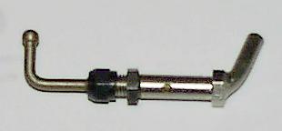
The needle assembly can be replaced with either a Cyclon F1C needle assembly (shown) or an ST assembly. Either needle body is a press-fit in the case. If you do replace the needle be aware that the fuel feed is a very small (0.5mm) hole that runs vertically down through the needle housing and into the rear of the shaft induction port. You can see the top of this hole on top of the needle housing in the centre of the flange - it is blocked by the needle body on top and lines up with the single hole on the bottom of the needle body. This engine operates with a dry venturi. If you replace the needle, be sure that the exit hole in the needle body lines up with feed hole and that the needle body does not have a second hole aligned with the drill hole on top of the casting!
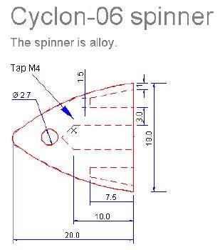
The engine comes as standard with a combat-style hex prop nut, tapped with an M4 thread. I've found this was not terribly suitable for use with a starter. As a result mine have been fitted with the streamlined spinner-shaped prop nut shown on the right. It is modelled on the spinners that used to be fitted to ED diesels and Shurikens.
Some batches of engines have their side stiffening flanges drilled with 2.1mm holes on 12 x 24mm centres. These are not intended as motor mounts, but as a place to attach flood-off valves, pacifier start valves, etc. to the engine. Makes for a neat setup!
If you're using a hard tank there's a convenient hex boss in the centre of the backplate. Your plug spanner will fit this boss to unscrew the backplate - nice touch! The boss can be tapped and drilled to take another brass nipple. The holes in these nipples are relatively large so remember that you can restrict it by blocking it with solder and then putting a really fine drill through the solder plug. This will stop the engine being flooded by back flow from the tank during refuelling. On the latest engines (since October 1999) the hex boss has been machined out to leave just a hex ring. Alexander says that he can supply the old-style solid boss backplate on special order and also confirms that there is no other place to fit a pressure tap on these engines.
 |
|
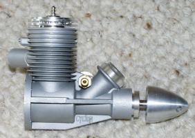
My TOP-2 fitted with the spinner, a flood-off
inlet nipple and an ST needle valve.
|
These notes are an accumulation of information about Cyclon-06 engines based on the experience of myself and others. It is an evolving document just as the Cyclons evolve from production batch to production batch. Information is added as and when it is discovered. These notes use metric units apart from the plug description because its a metric engine though it uses an American plug.
You'll need the special head and plug wrenches and a supply of Nelson plugs before you try to run the Cyclon.
The standard engine is set up for pacifier operation. To quote Alexander Kalmykov himself: "pressure system (fuel rubber tank about 1 kg/cm)". The engine is quite unlikely to run on suction with the fuel being fed in so far downstream of the venturi.
AAC engines are very tight - a new engine will probably squeak and may stick as you hand-turn it over Top Dead Centre. A Cyclon will be noticeably tighter without the plug fitted than with it screwed home. This is a consequence of the way the plug expands the head to make a more positive head seal. It is probably not a good idea to turn a new engine over without first fitting a plug.
Dave Clarkson says that an engine that squeaks and continues to do so even after it is broken in has a particularly round, good fitting piston/cylinder combination. He's a C/L team race guy so should know what he's talking about.
Initial running should be done on your intended contest fuel, the contest prop or smaller, and the engine should not be run too rich. The idea is to run the engine at its intended operating speed or faster under a fairly light load and to get it hot.
I started using 25% nitromethane, 25% synthetic oil and 50% methanol with an APC 6 x 2 propeller. George Aldrich doesn't recommend less that 20% oil in an AAC engine and thinks 25% is better, though that's pretty gooey stuff. My favourite oil is Klotz KL 100, now known as Super Techniplate, which is an 20:80 castor:synthetic oil mix. To buy Klotz oils in the UK, order from Model Technics. Their phone number is +44 (0)1702 292244. The order will be delivered to your nominated model shop and you pay when you collect it from the shop. The shop must be a Ripmax agent.
Run the engine slightly rich for the first few runs but avoid letting it 4-cycle. Don't run the engine lean either or it will damage itself due to insufficient top-end lubrication. Try leaning it out about the 3rd run and run it at max power as soon as it will hold the setting without sagging.
Once you've had a run or two holding maximum rpm for the full tank its ready to fly. Mine held its setting on the 3rd run.
Actually, on a hard tank setup I found that I couldn't get the engine to 4-cycle because that 0.5mm inlet hole restricts the fuel too much for that. Just as well - I've been told that they should not be allowed to 4-cycle during their first runs because when they are tight and cold the piston can pick up on the chrome bore and damage the chrome layer.
Expect to blow a plug on the first run and probably the second run too. That's pretty normal for an AAC.
You'll likely see a big rev increase through the first few runs - mine did something like 27000, 28500, 29000. Expect anything from 29000 to 30200 on the APC 6x2 and 20-25% nitromethane when its broken in.
If you have a set of Cyclon head shims you have the possibility of varying the compression ratio to suit the conditions on the competition day. This is done by adding or subtracting shims between the mating surfaces of the cylinder liner and the head to adjust the head clearance. Adding shims decreases compression and retards ignition timing, while removing them increases compression and advances ignition timing.
The factory settings seem to work reasonably well for 25% nitromethane and an APC 6x2. I haven't yet experimented with varying the head clearance so can't give specific guidance for the Cyclon-06, but here are some general notes. The optimum head clearance depends on a number of factors:
The traditional adjustment method is to add shims until the needle settings become critical and then take one out. The RPM will rise as you add shims if the engine is over compressed for your operating conditions. If you fly with too much head clearance you may suffer engine cuts during the climb. Flying with too little clearance is safe but may reduce the available power.
Be careful if you attempt to reduce the head clearance below the factory settings. The use of a micrometer depth gauge is strongly recommended if you do this, as you can cause serious damage if you reduce the clearance so far that the piston hits the head. Alexander's recommended head clearances are:
| Fuel | Engine | Head clearance |
| 20:80 FAI fuel | TOP-2 | 0.15...0.2mm |
| TOP-3 | 0.25...0.35mm | |
| 40% nitromethane | TOP-2 | 0.25...0.35mm |
| TOP-3 | 0.3...0.4mm |
From Doug Galbreath:
I have stumbled upon a possible problem with the TOP-3 061 and TOP-3 049 engines. In order to find out if yours is part of the problem, you must disassemble the engine and take out the crankshaft. Take a close look at the hole in the crankpin which is there for oil/fuel to flow into the rod bearing. Some engines have holes that are blocked by the plug that is pressed in from the rear to seal the hollow crankpin so that oil will flow to the rod.
To fix:
From John Lorbiecki:
Just ran into something that may be of interest to Cyclon owners. As many know, my son is on the Junior F1J team. Because of this we have been doing a lot of engine running. We had acquired two Cyclons from the Gunders. It so happened that one of them in particular had a problem in that it would not hold a needle valve setting. We kept reducing the compression with shims but it only helped a small amount. I modified the combustion chamber shape, which helped a small amount but still would not hold a setting. It would start, run for a short time, and then drastically change rpm. sometimes to the point of quitting. I was somewhat lost.
After a night of screwing around, I finally pulled the engine apart and started to look at it, micrometer in hand. everything looked fine. However, after measuring the piston, I found that the bottom of the piston measured 11.176 mm (.4400") diameter. However, the top was mushroomed out to 11.184 mm (.4403")! Using a machinist's stone, I worked on the piston carefully and slowly removed the mushroomed material until it was once again 11.176 mm (.4400") diameter. I also slightly broke the sharp edge at the top of the piston.
Note that this engine has much time on it. Craig stated to me that the engine always had a problem, to such a point that they could not get a full run on it and planted many a carbon tree because of bad runs.
After making the modification, the engine fired right up, needles very well, and runs pretty consistently through a full bladder. Problem solved! I looked at the other engine (note that both were rear exhaust versions) and it showed the same problem. I modified that piston also and I could suddenly add compression to it and soon it reacted the same, with a good needle valve range.
If you are having problems with needle valve setting (engine quitting after a short time running) look at the piston. Care must be taken as you can easily screw up the seal. Hope this helps our fellow flyers!!
Doug Galbreath adds:
John Lorbiecki is correct in his assessment and the cure of the .061. The problem lies in piston growth when the engine is heated up to running temperature. The piston growth thing does not happen to all engines, so don't assume that yours has done that. Breaking in the engine usually makes things fit, if you run it enough. Then, there's always the telephone or the e-mail if you are having problems.
I would caution users who have no real knowledge of piston fit, and methods of obtaining it, about using various means of achieving the correct fit. First, you should know the fit that is desirable, relative to the point where the piston sticks, dry, in the cylinder. This number is 1.65 mm (.065") below the top of the barrel. This is the number that seems to always work in F1J. Keep in mind that this number is attained by gently pushing the piston into the cylinder, clean and dry, with only about 225 g (8 oz.) of pressure. To attain this fit, the piston can be lapped in the cylinder with Bon Ami and oil or Ultra Brite toothpaste and water. Bon Ami is faster than Ultra Brite, but ultimately more dangerous. Go slowly, clean and check often, and don't get greedy. I do not recommend sandpaper. If you do use sandpaper, I have new pistons and liners in stock.
From Doug Galbreath:
I've been doing a bit of investigating on the Cyclon consistency problem. While a lot of them are very good, a few have been problematical, and the tapers vary from .0004" to .0009". No amount of careful break in and TLC in general will cure some of them. Turns out that some sleeves have a weird taper profile with a taper-straight-taper shape. The top of the bottom taper then turns out to be the seal area and it is about .100 in. from TDC. These engines run OK, but are not fast and they also burn plugs more frequently for no reason. They also don't like hot fuel, and they don't break in worth a hoot. Subsequently, I have fixed a bunch of them, and when they are done, they all run exactly the same. The trick is in the honing and measuring with the Sunnen gage. Takes about an hour on each engine to do the whole job.
. . . however, please let it be known that I do not fix them for nothing. It is enough that I have to do them for nothing in the engines that I sell. Also, there is no guarantee that all of the funny ones can be fixed, and also there is no guarantee that new liners will be any better. This has been happening for quite some time.